
Visits: 11
Unified Table Design for Enhancing HL7 R-MIM, HMD Structures, and Graph Walk
- 1. Overview
- 2. Design Features
- 3. Example Representation
- 4. Challenges in Implementing the Two-Table Approach: An Analysis of Study Report Part 2, Clause 4
- 5. Solutions with a Single Table Definition:
- 6. Steps for the Graph Walk in HL7 R-MIM to HMD
- 7. Example Message Information Model in HL7 Version 3 Message Development Framework
- 8. Enhancing Clarity in HL7 Data Structures
- 9. HL7 Graph Walk
- 10. Final Summary
- 11. Generating Unified Tables from Multiple CSV Sheets
Nobuyuki SAMBUICHI
ISO/TC295 Audit data services
Convener at SG1 Semantic model
Co-project leader at WG1 AWI 21926 Semantic data model for audit data services
1. Overview
The semantic model necessitates consistent, flexible, and concise message formats for effective data interchange. Addressing this, HL7 offers a robust representation and binding methodology through Graph Walk [1], transitioning from the Refined Message Information Model (R-MIM) to the Hierarchical Message Definition (HMD). However, the current representation using two tables can be verbose, leading to potential inconsistencies and a lack of clarity. To mitigate these issues, we propose a single-table design approach that effectively streamlines the representation. This approach captures the hierarchical relationship between super classes and their specialized counterparts in a clear, concise manner.
Despite the efforts of TC215/SC/WG2 in drafting ISO 17113:2004(E), a standard for Health Informatics focusing on message development, as a Final Draft International Standard (FDIS) in 2005, the standard was not completed and was eventually abandoned. This text revisits the original HL7 graph walk and introduces the Unified Table Design to bridge the gaps left by this unfinished standard.
The unified table design conforms to the HL7 10.2.2.2 Tabular Refined Message Information Model, modified to align with ISO/IEC 19505 OMG UML terminology. This design is versatile, applicable for both R-MIM and HMD tables. Additionally, open-source Python programs by JISC ensure the standard’s independence from proprietary design tools, enhancing its long-term maintainability.
2. Design Features
2.1. Hierarchical Structure
The design introduces a Level column to indicate the hierarchy of classes and their properties. Level 1 represents primary classes (e.g., Super Class and Specialized Class), while Level 2 details the attributes and associations of these classes.
2.2. Consistency
The unified table ensures that attributes and associations are consistently represented across both super and specialized classes. This eliminates redundancy and the need to re-specify properties for specialized classes when they inherit properties from the super class.
2.3. Flexibility
The design retains the flexibility of the HL7 framework, allowing for the easy addition of new specialized classes or properties without disturbing the existing structure.
3. Example Representation
| Level | Type | Class Name | Property Name | Multiplicity | Datatype | Associated Class | Description |
|---|---|---|---|---|---|---|---|
|
1 |
Super Class |
Activity |
|||||
|
2 |
Association |
Activity |
User ID |
1..1 |
BAS User |
The reference identifier for the person who did the activity. |
|
|
2 |
Attribute |
Activity |
Date |
0..1 |
Date |
The date of activity. |
|
|
2 |
Attribute |
Activity |
Time |
0..1 |
Time |
The time of activity. |
|
|
1 |
Specialized Class |
Created |
1..1 |
Activity |
A version of the Activity that has been input or recorded. |
||
|
1 |
Specialized Class |
Approved |
1..1 |
Activity |
A version of the Activity that has been validated or confirmed. |
||
|
1 |
Specialized Class |
Posted |
1..1 |
Activity |
A version of the Activity that has been made official or finalized. |
With this approach, the representation is clearer and reduces potential errors in interpretation. The design seamlessly integrates the detailed information of the R-MIM and the hierarchical structure of the HMD into a unified table, making it more straightforward to use for information exchange implementations.
4. Challenges in Implementing the Two-Table Approach: An Analysis of Study Report Part 2, Clause 4
Interoperability and clarity in data modeling are essential, especially when constructing and interpreting complex structures like the Refined Message Information Model (R-MIM) and Hierarchical Message Definition (HMD). In such scenarios, every byte of information matters, and any ambiguity or redundancy can lead to errors and confusion.
4.1. The Problem with Study Report Part 2 Clause 4 Two Table Approach
| Object class | Attribute term | Status | Representation | Description |
|---|---|---|---|---|
|
Activity |
User ID |
M |
Identifier |
The unique identifier for the person who did the activity. |
|
Activity |
Date |
O |
Date |
The date of activity. |
|
Activity |
Time |
O |
Time |
The time of activity. |
| Object class term from | E/R card. | Mult. From | Mult. To | Relation type | Object class term to |
|---|---|---|---|---|---|
|
Activity |
N:1 |
1..n |
1..1 |
Association |
BAS User |
|
Entered |
1:1 |
1..1 |
1..1 |
Specialization |
Activity |
|
Approved |
1:1 |
1..1 |
1..1 |
Specialization |
Activity |
|
Posted |
1:1 |
1..1 |
1..1 |
Specialization |
Activity |
4.2. Problems with Two-Table Definition:
To explain the problems with the two-table definition in the context of UML and how it differs from ER (Entity-Relationship) diagrams in relational modeling, let’s first understand the key distinctions between UML and ER diagrams:
4.2.1. UML vs. ER Diagrams:
While ER diagrams focus on the relational aspects of a database, UML class diagrams provide a more integrated view of both structure and relationships in a system. The two-table approach risks fragmenting this view and creating confusion, particularly when complex associations are involved. A unified table approach better aligns with UML principles, offering clarity and ease of interpretation.
Scope and Usage:
UML (Unified Modeling Language): UML is a comprehensive modeling language used in software engineering, covering a wide range of diagrams to represent different aspects of a system. It includes class diagrams, sequence diagrams, state diagrams, and more, offering a holistic view of both the static structure and dynamic behavior of a system.
ER Diagrams: ER diagrams are specifically focused on database modeling. They represent the entities (tables in a database), their attributes (columns), and relationships (foreign keys, many-to-many relationships) among them. ER diagrams are primarily used in designing and understanding relational database schemas.
Representation of Relationships:
UML: In UML, relationships (associations) are treated as first-class citizens, equally important as the entities (classes) themselves.
ER Diagrams: In ER diagrams, relationships are often represented more implicitly, primarily focusing on how entities are connected, typically through foreign keys.
4.2.2. Problems with Two-Table Definition in UML Context
Using two separate tables to represent attributes and relationships in a UML class diagram can introduce several challenges:
- Lack of Integrated View:
UML excels in providing an integrated system view. Splitting attributes and associations into separate tables may obscure the comprehensive structure and interactions of classes, contrary to UML’s holistic approach. - Confusion with ER Modeling:
Distinctly dividing attributes and associations could make UML representations resemble ER diagrams, potentially causing confusion. Unlike ER diagrams focused solely on static data structures, UML class diagrams also emphasize relationships and system interactions. - Complexity in Association Representation:
UML associations are often more complex than ER diagram’s foreign key relationships, entailing multiplicity, directionality, and other features. Their separation into a different table may oversimplify these elements, making them less comprehensible. Moreover, managing and updating two separate tables can increase maintenance complexity, heighten the risk of discrepancies, and complicate cross-referencing, especially for elements serving dual roles, such as ‘User ID’. - Potential Misinterpretation:
When an attribute in a class also references another class, similar to a foreign key in ER diagrams, separate tables can lead to ambiguity. It may become unclear if such an attribute is solely data-centric or indicative of a relationship, leading to potential misinterpretations. - Duplication and Overlap:
The two-table approach risks duplication and overlapping definitions, particularly when elements like “User ID” function as both an attribute and an association. This can cause uncertainty about their role, whether as an intrinsic class property or as a connector to another class.
Overall, these issues underscore the need for a more unified approach in UML modeling to maintain clarity, context, and the integrity of class structures and relationships.
5. Solutions with a Single Table Definition:
The proposed single-table design seamlessly merges the attributes and associations of UML class diagrams into a unified structure, effectively addressing the complications inherent in the two-table approach. This design enhances clarity and simplifies interpretation.
5.1. Unified Table Structure:
- Level: Indicates the hierarchy or the level of the class within the overall structure. For example, ‘1’ for primary classes and ‘2’ for their attributes or associations.
- Type: Specifies whether the entry is a ‘Super Class’, ‘Association’, ‘Attribute’, or ‘Specialized Class’. This helps in differentiating between the nature of each entry.
- Class Name: The name of the class to which the entry belongs, such as ‘Activity’.
- Property Name: For attributes and associations, this column names the specific attribute or association, like ‘User ID’, ‘Date’, and ‘Time’.
- Multiplicity: Defines the quantity of instances allowed for a property. For example, ‘1..1’ signifies a one-to-one relationship, while ‘0..1’ indicates that the property is optional.
- Datatype: Applicable for attributes, this column specifies the type of data each attribute holds, such as ‘Date’ or ‘Time’.
- Associated Class: Relevant for associations, this column identifies the class that the current class is associated with. For instance, the ‘User ID’ in ‘Activity’ is associated with the ‘BAS User’.
- Description: Provides a brief explanation or context for each attribute or association. This column is crucial for understanding the purpose and use of each property in the class.
5.2. The Proposed Single-Table Design
To address these challenges, a single-table design approach is proposed.
| Level | Type | Class Name | Property Name | Multiplicity | Datatype | Associated Class | Description |
|---|---|---|---|---|---|---|---|
|
1 |
Super Class |
Activity |
|||||
|
2 |
Association |
Activity |
User ID |
1..1 |
BAS User |
The reference identifier for the person who did the activity. |
|
|
2 |
Attribute |
Activity |
Date |
0..1 |
Date |
The date of activity. |
|
|
2 |
Attribute |
Activity |
Time |
0..1 |
Time |
The time of activity. |
|
|
1 |
Specialized Class |
Created |
1..1 |
Activity |
A version of the Activity that has been input or recorded. |
||
|
1 |
Specialized Class |
Approved |
1..1 |
Activity |
A version of the Activity that has been validated or confirmed. |
||
|
1 |
Specialized Class |
Posted |
1..1 |
Activity |
A version of the Activity that has been made official or finalized. |
5.3. Explanation of the Design:
- The table starts with the ‘Super Class’, ‘Activity’, setting the context for the entries that follow.
- It then details the associations and attributes of ‘Activity’, like ‘User ID’, ‘Date’, and ‘Time’, along with their characteristics and roles.
- The specialized classes like ‘Created’, ‘Approved’, and ‘Posted’ are extensions of the ‘Activity’ class, each representing a different state or version of ‘Activity’.
By consolidating all this information into a single table, the design enhances readability and comprehension. It allows users to see at a glance the relationships and properties of a class, along with detailed information like multiplicity and data types. This unified approach simplifies the understanding of the class structure and its various relationships, reducing the complexity and potential ambiguity associated with multiple tables.
5.4. Advantages of a Unified Table Approach in UML
A unified table approach in UML offers significant benefits over the traditional two-table method, addressing key issues and enhancing the overall modeling process:
- Clarity and Cohesion:
The unified table merges attributes and associations into one comprehensive view. This integrated perspective aligns with UML’s holistic approach, facilitating a clearer understanding of each class’s properties and relationships. - Clarifying Relationships:
By distinctly labeling properties as either attributes or associations, the unified table format effectively reduces ambiguity. It represents UML’s focus on detailed association treatment more accurately, making it easier to comprehend the nature of each relationship within the model. - Simplified Understanding and Maintenance:
The unified format’s straightforward structure simplifies both comprehension and maintenance. With all class-related information consolidated in one table, updates and changes are more manageable, ensuring consistency and minimizing errors. This approach significantly reduces maintenance efforts compared to managing separate tables for attributes and associations. - Enhanced Data Integrity:
A single, unified table reduces the risk of conflicting or inconsistent data representations. It allows for easier identification and correction of discrepancies, ensuring a more accurate and consistent depiction of class structures and their relationships.
In conclusion, the unified table approach in UML offers a more streamlined, clear, and integrated view of class structures and relationships. While the two-table format has its uses, it can introduce complexity and ambiguity, especially in models where relationships play a crucial role. By consolidating information into a single table, the unified approach enhances the understanding, maintenance, and integrity of UML class diagrams.
6. Steps for the Graph Walk in HL7 R-MIM to HMD
6.1. Overview
A step-by-step guide on how to perform a Graph Walk from the Refined Message Information Model (R-MIM) to the Hierarchical Message Definition (HMD) within the context of HL7 (Health Level Seven International) standards.
6.2. Choose the Root Class
It starts with the “Patient” as the root class or another class that has a mandatory relationship to the root class in the specified direction. It considers the relationships and cardinalities to determine the appropriate root class.
6.3. Build the Hierarchical Message Definition (HMD)
Step 1: Copy the class from R-MIM to HMD, including all attributes and associations that will or may appear in the message. Also, place the class on top of the LIFO list.
Step 2: Select another class related to the currently selected class and continue this process, following the rules specified (from Gen-to-Spec to None).
6.4. Deal with Cardinalities Greater than One:
If associations have cardinalities greater than one, create distinct message elements to represent the association as a set or a list.
7. Example Message Information Model in HL7 Version 3 Message Development Framework
7.1. UML Diagram
Following UML diagram illustrates a Message Information Model (MIM) specified in the HL7 Version 3 Message Development Framework.
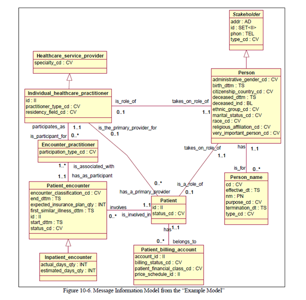
7.2. R-MIM Table:
The R-MIM (Refined Message Information Model) provides a detailed description of a specific use case, highlighting the classes, attributes, and associations pertinent to a given healthcare interaction.
HL7 has established the Tabular Refined Message Information Model, which we have streamlined to represent UML class diagrams in a concise tabular format.
10.2.2.2 Tabular Refined Message Information Model
Exhibit 10-1, at the end of this chapter, is an example of the tabular version of the Refined Message
Information Model shown in. It has two major sections:· The information model section, on the left, lists the information model entities (classes, associations, and attributes), one per row.
· The constraints and defaults section states specific constraints on the information model entities that will be applied to all message formats that are in Hierarchical Message Definitions derived from the Refined Message Information Model. Some of the constraints are also a part of the Message Information Model, although they may be tightened in the Refined Message Information Model. Many of the constraints are not UML constructs; they apply specifically to the HL7 messages defined based on the Refined Message Information
Model.Some column headings in the constraints and defaults section contain the number sign. This indicates that the value for a given cell can be stated in a separate list of constraints, defaults and comments that accompanies the Refined Message Information Model and its associated Hierarchical Message Definitions.
The columns that compose these sections are defined below.
10.2.2.2.1 Information Model Section
- Row Number. This column is the row number in the spreadsheet that is used to generate the tabular
format. It is useful during discussions about the spreadsheet.- Row type. This column identifies the kind of information model entity that the row represents. The
possible values are:rmim always the first row of the table, identifies the particular Refined Message Information Model in the nomenclature of the HL7 Repository
class identifies a “class” in the Refined Message Information Model attr identifies an attribute of the “class” that is most directly above this row
attr identifies an attribute of the “class” that is most directly above this row
assoc Identifies an association leading from the class that is most directly above this row
stc subtype constraint: this row corresponds to a subcomponent of the row above; it would not normally be included in an Refined Message
Information Model, but it is included in order to be able to state a constraint on the subtype. This is explained in 10.2.2.4.It is natural to believe that every row identified with assoc has a corresponding assoc row under the row that represents the distal class of the association. However, this is not always true. Where the committee has determined that the association will only be traversed in one direction the corresponding assoc row will not be present.
- Class or Property. This column contains the information model name of the entity that is described by the row. The term property is used to lump together attributes and associations. This is because they will be treated in a very similar manner in the Hierarchical Message Definition. In an rmim row, this column contains the identifier of the parent Message Information Model.
- Short name. This is an abbreviated form of the name of the information model entity that will be used to tag the corresponding message elements in ITS-specific syntaxes that use tags. In an rmim row, this column contains the name of the parent Message Information Model.
- Inherited from. This is the class where the property (attribute or association) appears in the Message Information Model. The column is only filled in when the property appears in a different class in the Message Information Model. See 10.2.2.3. In an rmim row, this column contains the name of the Refined Message Information Model.
- Message Element Type. For attributes, this is the data type of the attribute. For associations, this is the name of the distal class.
Following table shows selected columns for some classes from Exibit 10-1.
|
Row Number |
Row Type |
Class or Property (Attribute or Association) |
Inherited From |
MessageElementType |
Cardinality |
|
3 |
rmim |
C00_RIM_0092D |
|||
|
4 |
class |
Patient_encounter |
0..1 |
||
|
5 |
attr |
id |
II |
1..1 |
|
|
6 |
attr |
status_cd |
CV |
1..* |
|
|
7 |
attr |
encounter_classification_cd |
CV |
0..1 |
|
|
8 |
attr |
start_dttm |
TS |
0..1 |
|
|
9 |
attr |
end_dttm |
TS |
0..1 |
|
|
10 |
attr |
expected_insurance_plan_qty |
INT |
0..1 |
|
|
11 |
attr |
first_similar_illness_dttm |
TS |
0..1 |
|
|
12 |
assoc |
has_as_participant |
Encounter_practitioner |
1..* |
|
|
13 |
assoc |
generalizes |
Inpatient_encounter |
1..1 |
|
|
14 |
assoc |
involves |
Patient |
1..1 |
|
|
15 |
class |
Inpatient_encounter |
0..1 |
||
|
16 |
attr |
id |
Patient_encounter |
II |
1..1 |
|
17 |
attr |
status_cd |
Patient_encounter |
CV |
1..* |
|
18 |
attr |
encounter_classification_cd |
Patient_encounter |
CV |
0..1 |
|
19 |
attr |
end_dttm |
Patient_encounter |
TS |
0..1 |
|
20 |
attr |
expected_insurance_plan_qty |
Patient_encounter |
INT |
0..1 |
|
21 |
attr |
first_similar_illness_dttm |
Patient_encounter |
TS |
0..1 |
|
22 |
attr |
start_dttm |
Patient_encounter |
TS |
0..1 |
|
23 |
attr |
actual_days_qty |
INT |
0..1 |
|
|
24 |
attr |
estimated_days_qty |
INT |
0..1 |
|
|
25 |
assoc |
specializes |
Patient_encounter |
1..1 |
|
|
26 |
class |
Encounter_practitioner |
0..1 |
||
|
27 |
attr |
participation_type_cd |
CV |
0..1 |
|
|
28 |
assoc |
is_associated_with |
Patient_encounter |
1..1 |
|
|
29 |
assoc |
is_participant_for |
Individual_healthcare_practitioner |
1..1 |
|
|
47 |
class |
Patient |
0..1 |
||
|
48 |
attr |
id |
Set<II> |
0..* |
|
|
49 |
attr |
status_cd |
Set<CV> |
1..* |
|
|
50 |
assoc |
has_a_primary_provider |
Individual_healthcare_practitioner |
0..1 |
|
|
51 |
assoc |
is_a_role_of |
Person_as_Patient |
1..1 |
|
|
52 |
assoc |
has |
SetList<Patient_billing_account> |
0..* |
|
|
53 |
assoc |
is_involved_in |
Patient_encounter |
1 |
The data types detailed in the table are defined as per the following quotation:
6.2.2.2.2 Overview of defined data types
The following table tries to give a short overview of the defined data types that are commonly assigned to attributes. This table is neither complete nor detailed enough to provide anything more than a coarse overview. The complete and detailed definition of HL7 data types is found in the HL7 Version 3 Data
Type Specification. The RIM also contains a special subject area where data types are represented as information model classes.
Table 4. Defined Data Types Name
Symbol
Description
Boolean
BL
The Boolean type stands for the values of two-valued logic. A Boolean value can be either true or false.
Character String
ST
Used when the appearance of text does not bear meaning, which is true for formalized text and all kinds of names. Do not use this data type for attributes intended to contain free text. Scarcely any attribute will be declared directly as a Character String.
Encapsulated Data
ED
Can convey any data that is primarily meant to be shown to human beings for interpretation. Whenever attributes should contain text entered and shown to users, the Encapsulated Data type should be used, not the plain character string type. Encapsulated Data can be any kind of text, whether unformatted or formatted written language or other multi-media data. Instead of the data itself, an ED may contain only a reference (URL).
Instance Identifier
II
Used to uniquely identify some individual entity, a piece of data or a real world entity. Examples are medical record number, placer and filler order id, service catalog item number, etc.
Telecommunication Address
TEL
A telephone number or e-mail address specified as a URL. In addition this type contains a time specification when that address is to be used, plus a code describing the kind of situations and requirements that would suggest that address to be used (e.g., work, home, pager, answering machine, etc.)
Code Value
CV
Exactly one symbol in a code system. The meaning of the symbol is defined exclusively and completely by the code system that the symbol is from. Used primarily for technical concepts, concepts which is crucial to HL7 operations, and concepts which are defined or adopted under the discretion of HL7.
Concept Descriptor
CD
A descriptor for a real world (“natural”) concept, such as a finding, a diagnosis, or of any semantic field, that is not under the sole discretion of HL7. A given concept may be expressed in multiple terms where each term is a translation of some other term, or is a (re-)encoding of the original human readable text, that can also be sent in this data type. This data type is suitable for multi-axial code systems.
Integer Number
INT
Integer numbers are precise numbers that are results of counting and enumerating. Integer numbers are discrete, the set of integers is infinite but countable. No arbitrary limit is imposed on the range of integer numbers. Two special integer values are defined for positive and negative infinity.
Real Number
REAL
Fractional numbers as approximations to real numbers. Fractional numbers occur whenever quantities of the real world are measured or estimated, or where quantities are the result of calculations based on other floating point numbers. This type preserves the precision in terms of significant digits.
Physical Quantity
PQ
A dimensioned quantity expressing the result of a measurement. Consists of a floating point value and a physical unit. Physical Quantities should be preferred instead of two attributes expressing a number and a unit separately. Physical quantities are often constrained to a certain dimension. This can be by specifying some unit representing the dimension (e.g., m, kg, s, kcal/d, etc.)
Monetary Amount
MO
The amount of money in some currency. Consists of a value and a denomination (e.g., U.S.$, Pound sterling, Euro, Indian Rupee).
Point in Time
TS
A scalar defining a point on axis of natural time.
General Timing Specification
GTS
A data type used to specify the timing of events. Every event spans one time interval (occurrence interval), i.e., a continuous range of natural time between a start-point and an end-point in time. A repeating event is timed through a sequence of such occurrence intervals. Such timings are often specified not directly as a sequence of intervals but as a rule, e.g., “every other day (Mo – Fr) between 8:00 and 17:00 for 10 minutes.” GTS is treated as a primitive data type (like TS) where there is a special syntax for specifying time of day, day of week, repetition pattern, etc.
Ratio
RTO
A ratio quantity is a quantity that comes about through division of any numerator quantity with any denominator quantity (except zero). Ratios occur in laboratory medicine as “titers”, i.e., the maximal dissolutions at which an analyte can still be detected. Other Ratios are price expressions, such as dollar per gram.
Postal and Residential Address
AD
The main use of such declared data is to be printed on mailing labels (postal address,) or to allow a person to physically visit a location (residential address). The difference between postal and residential address is whether or not there is just a post box.
Person Name
PN
Used for one full name of a natural person. Names usually consist of several name parts that can be classified as given, family, nickname etc. This data type is intended to be used only in the Person_name class. Instead of directly using this data type for an attribute of another class, one should consider drawing an association to the Person_name class.
Organization Name
ON
Used to name an organization. Similar but simpler than the name of a natural person
Any type
ANY
Used where data of any data type can be sent. This data type must not be used except in very special cases where it needs extensive documentation as to how this can be used interoperable. Currently there is only one use for the ANY data type (i.e., the Observation.value). An attribute of ANY data types can be constrained in subordinate models (r-MIM, HMD).
Table 5. Generic (Parameterized) Data Types Name
Symbol
Description
Set Collection
SET
A collection of values of any type T without a specifying an order among the elements.
List Collection
LIST
An ordered set of values of any type T.
Bag Collection
BAG
An unordered set of values of any type T where each value can occur more than once (rare).
Interval
IVL
Ranges (intervals) of values of type T. An interval is a set of consecutive values of any ordered data type, such as, integer, floating point, point in time, physical quantity, monetary amount, and ratio.) Intervals should be preferred instead of two attributes expressing a start and an end separately.
Uncertain value using probabilities
UVP
A nominal value with a probability number indicating the level of certainty for the value to apply in the given context.
Parametric probability distribution
PPD
A probability distribution used to indicate certainty (accuracy) of a quantitative value. Allows specifying a distribution type and applicable parameters. All distribution types have the parameters mean and standard distribution. The mean is the value that would be reported if no probability distribution were available.
7.3. Partial Listing of the Resultant HMD Table:
Below is a selection from the HMD table, showcasing a subset of the results obtained from the HL7 graph walk based on the previous example. For associations, the message element name merges the association’s name with its associated class name. Additionally, a new “Item” type has been introduced to manage associations with cardinalities greater than one.
| row type | message element name | in message element type | source of message element | of message element type | Card. |
|---|---|---|---|---|---|
|
assoc |
is_involved_in_Patient_encounter |
Patient |
New type |
Patient_encounter |
1..1 |
|
attr |
encounter_classification_cd |
Patient_encounter |
Data type |
CV |
– |
|
assoc |
has_as_participant_Encounter_practitioner |
Patient_encounter |
New type |
Set<Encounter_ practitioner > |
1..1 |
|
item |
_Encounter_practitioner |
Set<Encounter_ practitioner > |
New type |
Encounter_practitioner |
|
|
attr |
participation_type_cd |
Encounter_practitioner |
Data type |
CV |
– |
Explanation:
assoc Row:
It’s showing an association between “Patient” and “Patient_encounter.”
The message element type is “Patient,” derived as a new type, and it`s associated with “Patient_encounter.”
attr Row:
An attribute row where the “encounter_classification_cd” attribute is part of the “Patient_encounter” message element, with data type CV.
assoc and item Rows for Cardinalities Greater than One:
For associations, like the association between “Patient_encounter” and “Encounter_practitioner,” a new type, “Set<Encounter_practitioner>,” is created.
An “item” row type is added, with the message element name “_Encounter_practitioner” representing the entity within the set.
8. Enhancing Clarity in HL7 Data Structures
HL7 standards typically utilize a shared column for both attributes and associations within their data structures. However, in this unified table approach, we have extended the column dedicated to associations and their associated classes. This modification allows users to more easily distinguish between properties and their relationships.
In this enhanced format, what was previously labeled as “Attribute/Association” is now renamed as “Property Name.” This change simplifies understanding and improves clarity. Additionally, the “Data Type” and “Associated Class” are now separated into distinct columns, offering a more organized and straightforward representation.
The table presented here offers a clear and concise representation of the Unified Modeling Language (UML). It lists each class along with its specific attributes, associations, and data types in a structured manner. Moreover, a dedicated “Cardinality” column is included, which represents the nature and strength of the relationships between the classes involved in each association. This comprehensive format ensures a more accessible and intuitive understanding of the complex relationships and elements within the HL7 standards.
9. HL7 Graph Walk
The following outlines the steps in the HL7 Graph Walk process. It begins with selecting the root class, progresses to copying classes and attributes from the R-MIM to the HMD, and addresses associations with cardinalities exceeding one. This structure encapsulates the message’s content and structure and serves as a guide for both implementation and documentation in health information exchanges.
Below, you’ll find an in-depth, step-by-step breakdown of the Graph Walk procedure, complemented by examples and outcomes for each phase.
9.1. Choose the Root Class
Action
Subject Class: Patient
Given the relationship and cardinality, Patient is the root class. Push ` Patient ` onto LIFO list
Result
Root class selected: Patient
| row type | message element name | In message element type | source of message element | of message element type |
|---|---|---|---|---|
|
(empty) |
| Patient |
|---|
9.2. Constructing the Hierarchical Message Definition (HMD) Using Graph Walk:
Step 1
Action: Transfer the Patient class to the HMD and remove it from the LIFO list.
Result: The Patient class is added to the HMD.
| row type | message element name | In message element type | source of message element | of message element type |
|---|---|---|---|---|
|
assoc |
is_involved_in_Patient_encounter |
Patient |
New type |
Patient_encounter |
Push Patient_encounter onto LIFO list.
| Patient |
|---|
|
Patient_encounter |
Step 2
Action: Select a class related to Patient. For instance, select Patient_encounter based on the mandatory relationship.
Result: Patient_encounter class is added next in the HMD.
9.3. Continuing with Step 1 and 2:
Action: From Patient_encounter, pick an attribute, e.g., encounter_classification_cd.
Result: This attribute is added to the HMD table.
| row type | message element name | In message element type | source of message element | of message element type |
|---|---|---|---|---|
|
assoc |
is_involved_in_Patient_encounter |
Patient |
New type |
Patient_encounter |
|
attr |
encounter_classification_cd |
Patient_encounter |
Data type |
CV |
Push Encounter_practitioner onto LIFO list.
| Patient |
|---|
|
Patient_encounter |
|
Encounter_practitioner |
9.4. Dealing with Cardinalities Greater than One
Action: Encounter an association with cardinality greater than one between Patient_encounter and Encounter_practitioner.
Result: Create distinct message elements to represent the association as a set or list.
| row type | message element name | In message element type | source of message element | of message element type |
|---|---|---|---|---|
|
assoc |
is_involved_in_Patient_encounter |
Patient |
New type |
Patient_encounter |
|
attr |
encounter_classification_cd |
Patient_encounter |
Data type |
CV |
|
assoc |
has_as_participant_Encounter_practitioner |
Patient_encounter |
New type |
Set<Encounter_practitioner> |
|
item |
_Encounter_practitioner |
Set<Encounter_ practitioner > |
New type |
Encounter_practitioner |
The association has_as_participant_Encounter_practitioner from Patient_encounter is of type Set<Encounter_practitioner>, reflecting the cardinality greater than one.
A new item row is added to the HMD to represent the Encounter_practitioner entities within the set.
After processing Encounter_practitioner, pop it off the LIFO list.
| Patient |
|---|
|
Patient_encounter |
After processing Patient_encounter, pop it off the LIFO list.
| Patient |
|---|
After processing Patient , pop it off the LIFO list.
| (empty) |
|---|
Now the Graph Walk has been corrected to ensure the LIFO list is emptied at the end of the process.
9.5. Continuing Steps:
You will continue the steps of the graph walk, copying classes, attributes, and associations to the HMD, and following the LIFO list until it’s empty, which signals the completion of the process.
| row type | message element name | In message element type | source of message element | of message element type |
|---|---|---|---|---|
|
assoc |
is_involved_in_Patient_encounter |
Patient |
New type |
Patient_encounter |
|
attr |
encounter_classification_cd |
Patient_encounter |
Data type |
CV |
|
… |
||||
|
assoc |
has_as_participant_Encounter_practitioner |
Patient_encounter |
New Type |
Set <Encounter_practitioner> |
|
item |
_Encounter_practitioner |
Set <Encounter_practitioner> |
New type |
Encounter_practitioner |
|
attr |
participation_type_cd |
Encounter_practitioner |
Data type |
CV |
|
… |
10. Final Summary
The HL7 graph walk procedure currently employs distinct formats for R-MIM (Refined Message Information Model) and HMD (Hierarchical Message Definition), leading to challenges in user comprehension. The inability of ISO 17113 to effectively redefine these two tables for graph walk purposes has been a notable shortfall. However, this unified table design addresses the issue by adopting a consistent format for both R-MIM and HMD, thereby simplifying the understanding for business experts.
Through these systematic steps, all necessary information and data elements are captured in the HMD, ensuring a comprehensive representation of the HL7 message structure, content, and associations according to the specific R-MIM and use case at hand. The LIFO list helps in managing and tracking the classes being considered during the graph walk process. Each step is essential to ensure that the final HMD is complete and accurate, facilitating effective and standardized health information exchange.
11. Generating Unified Tables from Multiple CSV Sheets
IBM Rational Rose, previously integral to the HL7 Message Development Framework Version 3.3 in December 1999, is now unsupported, underscoring the perils of depending exclusively on proprietary software. This development stresses the need for flexible, non-proprietary tools in crafting durable semantic models for standards. Initially, IBM provided a complimentary migration path from Rational Rose to Rational Software Architect in early 2005. However, as of May 19, 2010, this transition became a paid service, reflecting IBM’s evolving software modeling strategies. The specifics of this shift are detailed in IBM’s software announcement letter RTL10038, issued on March 17, 2010.
Figure 2. Example of a model in RoseTree view
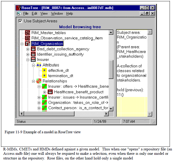
Additionally, a proprietary graphical design tool caters to ISO 21377 and other extensions, capable of generating multiple CSV files for the ISO/AWI project. JISC-developed Python scripts, particularly ObjectClass.py, play a critical role in assembling a unified table sheet that merges UML object classes and properties. This table, editable by experts, serves as the R-MIM for the HL7 graph walk process. Complementing this, the HL7graphWalk.py script conducts the graph walk, producing a Hierarchical Message Definition (HMD), a hierarchical logical model.
11.1. ObjectClass.py
| IN | Program | OUT |
|---|---|---|
|
Directory: ./object_class/ |
ObjectClass.py |
Directory: ./semantic/ |
|
Note
|
For those interested in exploring further, the Python source code is available for access on GitHub. |
11.2. HL7graphWalk.py
| IN | Program | OUT |
|---|---|---|
|
Directory: ./semantic/ |
HL7graphWalk.py |
Directory: ./semantic/ |
|
Note
|
For those interested in exploring further, the Python source code is available for access on GitHub. |
11.3. Purpose of These Open-Source Programs
The primary objective of these open-source Python programs is to facilitate a more efficient and transparent process in data handling and analysis within the field of semantic model development. The programs are designed with the following goals in mind:
- Enhanced Data Integration: By generating unified table sheets from multiple CSV files, these programs aim to streamline the integration of diverse data sets. This integration is crucial for complex projects where data consistency and accuracy are paramount.
- Ease of Use and Accessibility: Open-source availability on GitHub ensures that these tools are easily accessible to a wide range of users, from professional developers to academic researchers. This accessibility fosters a collaborative environment where improvements and customizations can be shared and implemented by the community.
- Standardization in Semantic Modeling: The tools support TC 295 audit data services data modeling, helping users in adhering to these standards in their projects. This standardization is vital for ensuring compatibility and interoperability in health data exchange.
- Facilitation of HL7 Graph Walks: The
HL7graphWalk.pyscript, in particular, is instrumental in executing HL7 graph walks. This process is key to producing hierarchical logical models (HMDs), which are essential in structuring and understanding audit data more effectively. - Expert Involvement and Customization: The ability to manually edit the unified tables ensures that expert input can be incorporated, allowing for tailored solutions that meet specific project needs. This flexibility is crucial in a field as dynamic and varied as health informatics.
- Support for Jurisdictional Localization and Extension: This design framework intends to facilitate further jurisdictional localization and extension. However, the implementation of these functions is currently pending due to the absence of a standardized extension framework for audit data services. We are prepared to support these functions as soon as the standard for extension becomes available.
In summary, these open-source programs are not just tools for data manipulation; they are part of a larger effort to improve the standardization, accessibility, and efficiency of health informatics practices worldwide, with a readiness to adapt to future developments in standardization and data services.

